
There is no doubt that helicopters are an incredible piece of engineering, but without their engines, they would be useless. Providing an engine that is lightweight, powerful, fuel-efficient, and reliable is paramount for it to work successfully in a helicopter.
Helicopter engines can be either piston or gas turbine turboshaft. Air is drawn in, compressed, mixed with fuel, ignited, then the rapid expansion of the gas is harnessed to turn a drive shaft which is fed to the main transmission. The engines use gasoline (Avgas) or Kerosine (Jet A1) to power them.
The size of the helicopter will dictate which type of engine and how many of those engines are used. There are pros and cons to each type of engine, but both types are highly engineered and well-tested to ensure they meet the highest quality standards – If they didn’t, there is no way I would strap my butt to one!
Let’s take a look at these different types of helicopter powerplants…
Types of Helicopter Engine
As briefly mentioned, there are two types of helicopter engines:
- Piston or Reciprocating Engine
- Gas Turbine Turboshaft Engine
This article will break down each engine type, how it works, the components that make it work, and how it drives the helicopter.
Piston Helicopter Engines:
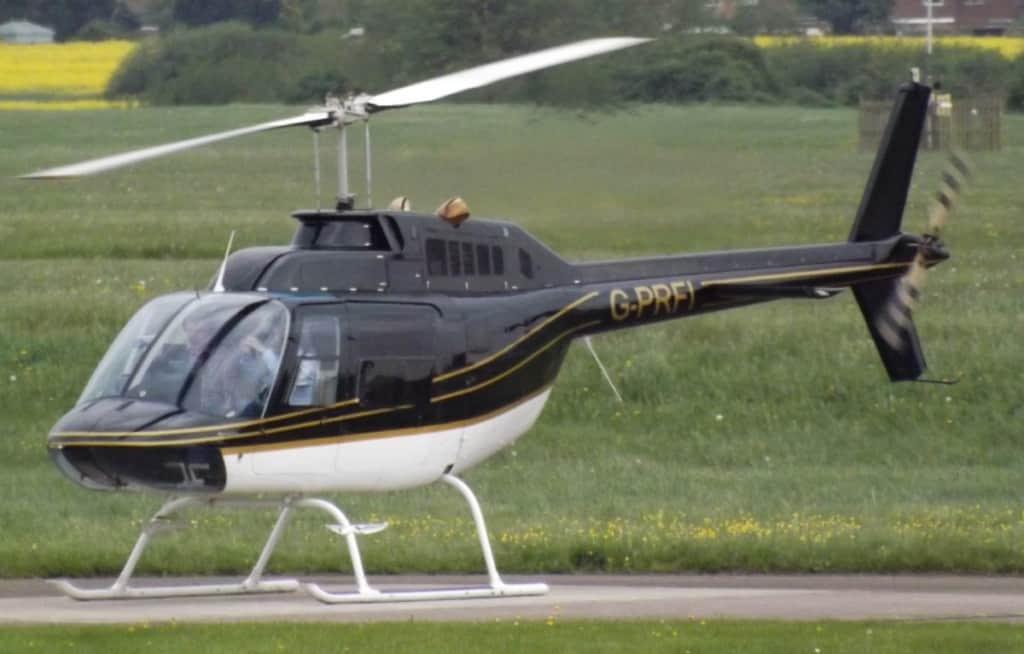
Piston helicopter engines are used mainly in today’s smaller, modern helicopters up to around 5 seats and weighing no more than around 2500 lbs (1135 kg). Before the advancement in gas turbine technology, piston engines were used in bigger helicopters like the early model Westland Whirlwind HAR.5s of the 1950s.
Today’s helicopter piston engines are normally 4 or 6 cylinders, horizontally opposed designs running on aviation gasoline, more commonly known as Avgas. They are incredibly reliable, but heavy compared to the power they create. For this reason, they are limited to the smaller helicopters.
How Do Piston Helicopter Engines Work?
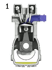
The piston engine on a helicopter is very similar to the engine in your car. Air is sucked into the engine through a carburetor or an air intake for the models that are fuel injected. This type of engine is a 4 stroke engine, which has 4 stages of operation.
Once the engine has started:
- Intake Stage – As each piston in its respective cylinder is drawn downwards by the crankshaft, a valve (Intake Valve) at the top of the cylinder is opened and air is sucked into the cylinder along with atomized fuel – Both are measured to provide the optimal ratio of fuel to air.
- Compression Stage – Once the piston reaches the bottom of the cylinder it then begins to rise back up the cylinder. At this point, the intake valve closes and seals the cylinder. This causes the fuel/air mixture to become increasingly compressed as the piston rises.
- Power Stage – Just as the piston reaches the top of its travel a spark plug fires and ignites the explosive fuel/air mixture. This causes the gas to rapidly expand and dramatically increase its pressure, forcing the piston back down the cylinder.
- Exhaust Stage – The piston reaches the bottom and momentum and the other cylinders firing cause the crankshaft to continue rotating and the piston begins rising back up its cylinder. At this point, another valve (Exhaust Valve) opens to allow the spent gas to exit the cylinder. As the piston reaches the top of its travel, the exhaust valve closes and the cylinder is ready for the next cycle.
The animation you see is just one of the 4 or 6 cylinders that make up a typical helicopter engine. The other difference is that the cylinders lie horizontal with the crankshaft running through the middle of the engine block. This allows the engine to be compact and cooled easily because the tops of the cylinders can be placed into airflow more easily by the helicopter designer.
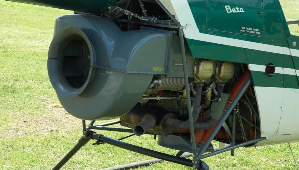
In this image, you can see the 2 right-hand cylinder covers (Bronze Colored Squares) of this 180hp, derated to 145hp Lycoming O-360 engine. To create enough cooling airflow, Frank Robinson (The original designer of this helicopter) created this fan shroud that pulls in air from the large round air inlet, goes through an engine-driven, squirrel-cage fan, and then blows across the cylinders to keep them cool, especially when the helicopter is hovering and there is no airflow from forward flight.
The crankshaft from the four pistons then connects to the drive system to power the helicopter.
How Does a Piston Helicopter Engine Drive The Transmission?
Once the engine starts, its driveshaft begins to immediately start rotating. The main problem here is that to get the main rotor system turning as soon as the engine starts would be too much drag on the engine and it would not start.
So, to allow the engine to easily start the helicopter’s main drive system is disconnected from the engine until the pilot activates the drive-engagement system.
The main way that a piston helicopter connects to the drive system of the helicopter is by a belt drive.
A grooved pulley is connected to the engine and a second grooved pulley is connected to the input driveshaft for the transmission. When the helicopter starts, the v-belts are loose, allowing the engine pulley to rotate without driving the v-belts.
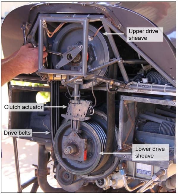
Once the engine has started, the pilot activates the ‘Drive-Engagement’ system via a switch on the instrument panel. There are a few different belt tensioning systems on piston helicopters but they all do the same job.
The system will then begin to tighten the v-belts, either by activating a motor and gearbox to push the two pulleys away from each other, thus tightening the v-belts, or by an electric linear actuator that moves an idler pulley and pulls the v-belts tight.
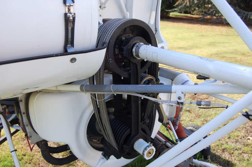
Once activated, the system will stay locked to keep the correct tension on the belts. Some systems, like those on the Robinson helicopters, monitor the belt tension and will automatically adjust the pulleys when in flight to maintain proper tension.
After the pilot has landed at the end of the flight, they will de-activate the tension system via the switch, and the motor will remove the tension from the v-belts, thus allowing the engine to be shut down while the main rotor is still spooling down.
Join My Newsletter & Get Great Tips, Information and Experiences To Help You Become a Superb Pilot!
Components of a Piston Helicopter Engine
Many of the piston engines used in today’s helicopters are very similar in design. They come in either carburated or fuel-injected models depending on the helicopter model.
Here are the main components of a typical helicopter piston engine:
Engine Block
Comprising of 4 or 6 cylinders, depending on the model, mounted flat at 180° to one another, known as ‘Horizontally Opposed’.
In the image you see here is a Lycoming O-360 reciprocating aircraft engine. This one is mounted to a Piper PA-28 airplane, but it is the same that powers the Robinson R22 Beta II series of helicopters. This image gives a great view of its layout.
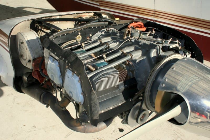
The crankshaft runs through the middle of the engine block, the same as the camshafts that operate the intake & exhaust valves. Instead of where the propeller connects to the shaft, a vee pulley is connected in the helicopters. The two tubes running to each cylinder are the pushrods that open and close the intake and exhaust valves, and the fins you see near the ends of the cylinders are to give each cylinder maximum surface area for cooling.
Starter Motor
Does exactly what it sounds like. When the pilot turns the ignition key to ‘Start’ or presses the ‘Start Button’ the starter motor extends a toothed gear and starts it rotating under very high torque.
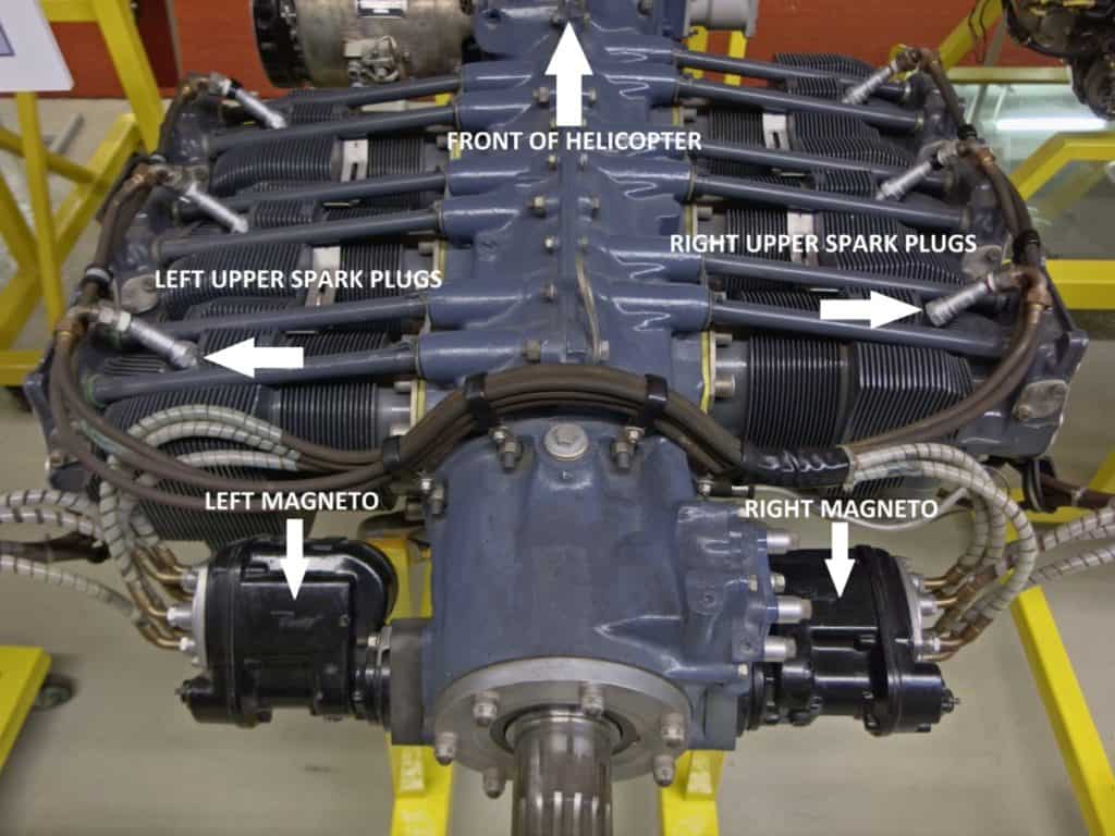
On the image above you can see the teeth surrounding the edge of the large flywheel. It’s these teeth that the starter motor engages with and beings to turn the engine over. The starter motor is hidden from view on the far right side of the engine.
Once the engine fires up, the button or key is released by the pilot, and the starter motor retracts its gear from the flywheel and stops rotating. The starter motor is no longer required for the remainder of the flight.
Alternator
The alternator is driven by a small v-belt off the main crankshaft. You can see the alternator just to the bottom left of the propeller in the photo above. The job of the alternator is to produce DC electrical power as soon as the engine crankshaft starts rotating.
The electrical power it generates is used to power all the aircraft lights, radios, GPS, instrumentation, and any electrical systems like the Drive-Engagement System, also referred to as the ‘Clutch’.
The second job the alternator has is to charge the battery. After every engine start the battery voltage becomes lower. To prevent the battery from becoming discharged over time and to be able to start the helicopter every time, the alternator recharges the battery during flight.
Magnetos
Magnetos are an engine-driven, electrical power-producing devices used to provide energy to the spark plugs to make them spark. There are two magnetos on the helicopter engine and each one operates independently of the other.
There are two spark plugs in each cylinder. One magneto supplies energy to one spark plug in each cylinder and the second magneto supplies energy to the other spark plug in the cylinders. Think of it as a set of upper spark plugs and a set of lower spark plugs. One magneto supplies the upper plugs, the other supplies the lower plugs.
Having the two independent systems allows for redundancy. If one fails, the other system can keep the engine running, albeit not as efficiently, but enough to get the helicopter home at slightly reduced power.
The nice things about the magnetos are that as long as the engine is turning, they will be producing the spark energy. They do not require any other outside influence which makes them great devices as they will still continue to operate if the aircraft has a total electrical failure.
Carburetor Heat
For the normally aspirated helicopter engines, they use a carburetor to mix the fuel and air to the correct ratio before it gets sent to the cylinders for combustion. When the helicopter requires more power, the carburetor’s butterfly valve opens and the suction from the intake stroke of the cylinders pulls in more air, by doing so, the venturi effect on the fuel line, pulls more fuel in too.
More Air and Fuel = Bigger Bang = More Power
When the air passes through the carburetor it naturally cools as part of the venturi process and it can cool by as much as 20°C. The problem with aircraft is that when they climb in altitude the ambient air temperature becomes colder. Once the aircraft begins to ingest cold, moist air ice can begin to form in the carburetor. Left to build, the ice will begin to close the gap used to ingest air and starve the engine of air and shut it down – Not good!
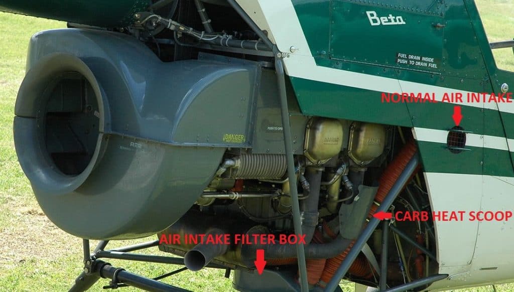
To overcome this, a simple scoop collects hot air from around the engine exhaust and directs it to the air intake of the carburetor. This increases the temperature of the air going into the carb and can either prevent the ice build-up or help melt the ice.
The carb heat system is monitored by the pilot via a temperature gauge. The yellow arc dictates when temperatures are prime for carb icing.
The system is activated by pulling a lever in the cockpit to direct the warm air into the carb.
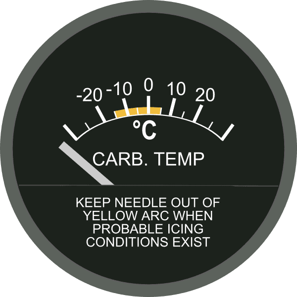
The carb air heat system is used before any reduction in power changes are made as the warmer air going into the engine reduces the power it produces.
1 minute – 30 seconds before reducing power, the flight manual recommends activating the system to melt any ice before the butterfly valve begins to close as the pilot reduces power. If ice is present, the gap between the butterfly valve and the wall of the carb can be completely closed off as the valve closes – This will cause the engine to stop.
A simple system that works well WHEN used correctly by the pilot. Many pilots have been killed due to carb icing when they forgot to activate the system before reducing power and their engine quit from air starvation.
Fuel Injection System
For increased engine performance many helicopter engines come with a fuel injection system rather than a carburetor system. One of the main benefits of a fuel injection system is that it helps eliminate any icing problems of the carb because there is no carb!
Fuel injection is exactly what it sounds like – It’s a system that injects fuel directly into each cylinder. The fuel is metered and injected at the correct time in the 4 stroke cycle via a fuel nozzle that atomizes the fuel as it dispenses.
The system uses a fuel pump to pressurize the fuel coming from the tank. It then goes through a valve that is also linked to the air intake valve, so when the pilot requires more power, it opens both the air intake and fuel flow valves to allow more air and fuel to pass into the engine.
The fuel is then sent to a distribution unit that directs it to the right cylinder at the right time. The air still goes to each cylinder via the air intake valve. Instead of mixing the air and fuel in the carburetor, the mixture is now mixed directly in the cylinder.
Because the fuel is metered and dispensed, increased performance and efficiency can be achieved using electronic systems to monitor and control the fuel flow to each cylinder.
Gas Turbine Helicopter Engines
The gas turbine engine is the powerhouse of helicopter propulsion. The lightweight, compact design and high power output make them perfect for installation in a helicopter – But they are not cheap! Even the small ones start at the same price as an entire piston-powered helicopter!
The type of gas turbine engine used in helicopters is called a ‘Turboshaft’ gas turbine and this means that it harnesses the engine’s power and then sends that power to a drive shaft which the helicopter can then use to drive the transmission system.
Helicopters can have 1, 2, or even 3 gas turbine engines installed depending on their weight and design. Let’s go take a look…
How Do Gas Turbine Helicopter Engines Work?
There are two types of gas turbine engine designs used in helicopters.
1. The first is the Allison series which uses a kind of reversing airflow design:
Air is pulled in from the front, sent to the back of the engine then moved through the middle of the engine, and then exhausted out of the top. This type of engine is very common on Bell helicopters.
2. The second kind of gas turbine is more of a straight-through airflow design and is more widely used:
Air enters through the intake and moves directly though the engine before exiting out the back.
Both engines use the same operating principle but differ in how their components are laid out physically.
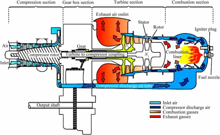
Gas turbine engines work by pulling air into the front of the engine by a compressor. Most turboshaft helicopter engines have a two-stage compressor. This compresses the air, heats it, and increases its velocity.
The compressed air is then sent into the combustion chamber where it is mixed with atomized jet fuel and ignited. Once the engine is running the fireball keeps the engine self-sustaining providing the fuel keeps coming.
The gas rapidly expands and is pushed through the gas generator turbine/s. These turn in the airflow and connect to the compressor on the front of the engine. This keeps the compressor turning to bring in more air to keep the engine running.
After passing through the gas generator turbine, the gasses pass through the power turbine/s. The power turbines are not connected to anything in the engine except a gearbox that feeds a drive shaft that is used to drive the helicopter transmission. This is where the power is harnessed.
After passing through the power turbine/s the gas exits the exhaust of the helicopter.
Providing fuel is constantly added the engine feeds itself and stays running in an endless cycle. If more power is required, more fuel is added which makes a bigger bang, which spins the gas producer turbine faster, which spins the compressor faster, pulling in more air to mix with the increased fuel.
More Air and Fuel = Bigger Bang = More Power
How Does a Gas Turbine Helicopter Engine Drive The Transmission?
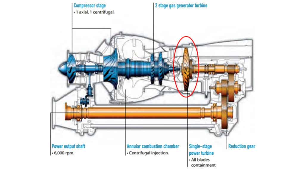
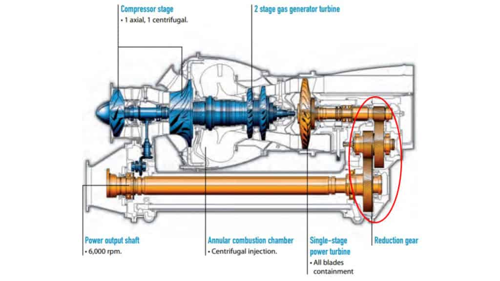
Depending on the design of the engine will depend on how the power is harnessed from the engine. Some turboshaft engines will have the power turbine connected to a gearbox that drives a drive shaft, or some can send a driveshaft out of the front or back of the centerline of the engine which can then be inserted into a gearbox mounted on the engine.
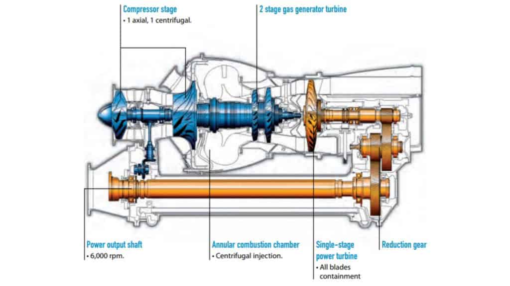
In the diagram below, the power turbine connects to the reduction gearbox right behind the power turbine. Drive (Orange) can be accessed from both the front and rear of this engine.
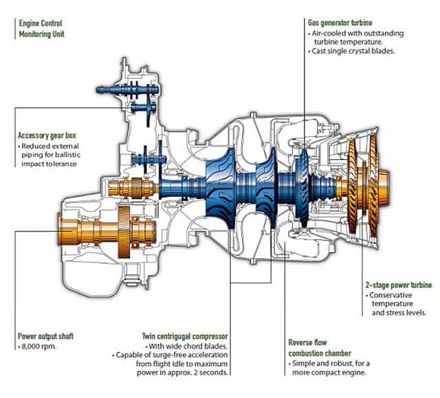
In the diagram below, the power turbines send a driveshaft through the center of the engine, and the reduction gearbox is located at the front of the engine. Drive (Orange) can only be accessed at the front of the engine:
Once the drive of the engine is accessed it is then just a matter of mounting a drive shaft between the engine and main transmission of the helicopter. When two engines are used they are mounted side by side and each driveshaft feeds into either side of the main transmission.
Unlike piston-powered helicopters, helicopters with a gas turbine engine do not need a clutch system to separate the engine from the transmission. Gas turbines allow the engine to start and begin rotating without turning the main rotor system because the Power Turbine/s are known as free turbines.
Even though the rest of the engine components are turning, the power turbine/s are only connected directly to the main transmission and will only turn when the gas flow through them is powerful enough to overcome the drag of the transmission. When the engine first starts, the flow of gas through the power turbine/s is low in volume, the air just passes through the power turbine blades without imparting any force onto them.
As the engine rpm increases during start, the volume of air passing through the power turbine increases, and at around 25% engine rotational speed, the gas flow will be strong enough to begin rotating the power turbine, which then drives the transmission, which in turn drives the main & tail rotors.
Components of a Gas Turbine Helicopter Engine
Although gas turbine engines look complex, their operation is quite simple. The components that make up a gas turbine engine are engineered to very tight tolerances to be able to handle the immense speeds and temperatures these things operate at.
For this explanation, we will look at the Arriel 1D1 engine that powers the AS350 B2 Astar. This is the one I’m currently flying and have lots of pictures of to help explain. Let’s start at the front of the engine and work our way through:
Compressors
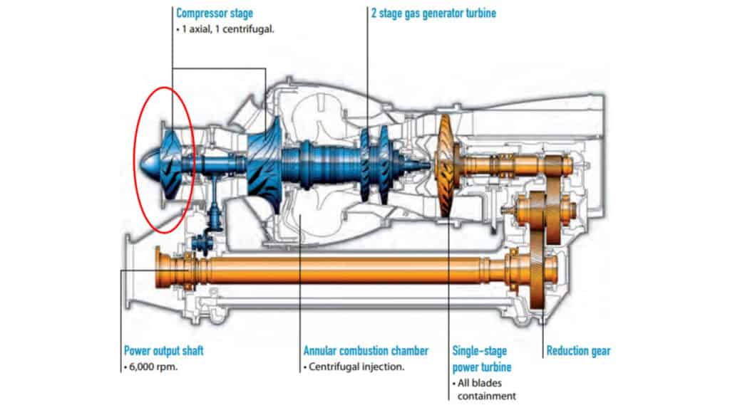

Most gas turbine helicopter engines consist of a pair of compressors at the very front of the engine. The first compressor is an Axial Compressor. This compressor’s job is to suck in the air and begin to increase its pressure and velocity. It also smooths out the airflow ready for it to enter the second compressor – The Centrifugal Compressor.
The centrifugal compressor then increases the air pressure again and raises its temperature before it enters the combustion chamber.
Both compressors are mounted to the same shaft and spin together as one unit. Their speed is controlled by the Gas Generator Turbine (More on this later).
Bleed Valve
The bleed valve is located on top of the engine between the axial and centrifugal compressors.
The compressors of the engine are designed to work at maximum efficiency when at high RPM. During start and low power settings, the air flowing through the compressors is very slow and can cause the rotor blades of the compressors to aerodynamically stall.
To prevent the stall the bleed valve is held open by a spring to unload the compressor at engine start, acceleration, and low power settings. By doing this the compressor senses less restriction and runs more efficiently. As the engine rpm increases the valve is closed using air pressure generated by the engine. It’s a fully automatic system and works very well.
Combustion Chamber
Once the air has been prepared by the compressors it enters the combustion chamber where atomized jet fuel is metered into the chamber from two fuel nozzles.
During engine start, the fuel and air mixture is ignited by two spark plugs. Once the engine reaches around 45% of its operating rpm the fireball in the combustion chamber is self-sustaining. At this point, the spark plugs are turned off for the remainder of the flight. Providing fuel keeps entering the combustion chamber the fireball will stay lit.
As the fuel/air mixture is ignited it rapidly increases its volume and the only way for it to escape is towards the back of the engine.
Fuel Control Unit
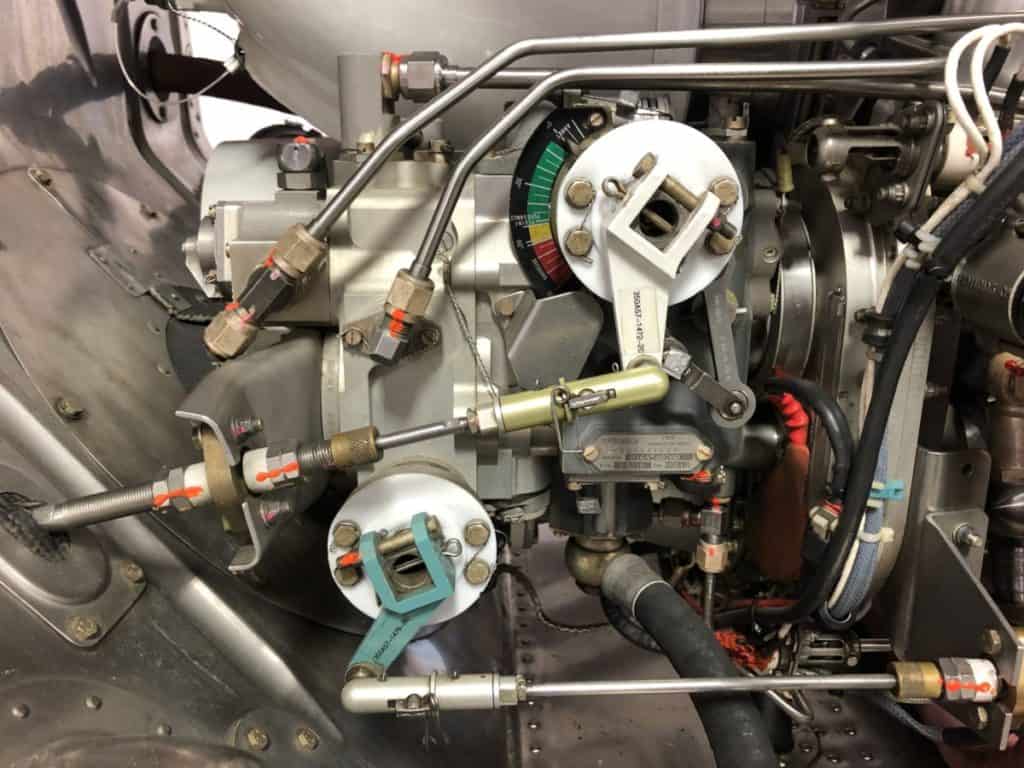
The fuel control unit sits on the front, lower part of the engine and is driven off the engine’s Accessory Gearbox. Fuel enters the control unit from boost pumps located in the helicopter fuel tank. The fuel control unit itself is a complex heart of the engine, but ill try and keep it simple to understand!
The fuel control unit is operated by two requirements:
- The Fuel Control Lever (Upper Linkage) – This is used for starting and accelerating the engine up to flight RPM. Once at flight RPM, the lever stays in that position for the remainder of the flight.
- The Collective is what the pilot uses to climb and descend the helicopter. As the blade pitch increases on the main rotor blades they create more drag. To keep the main rotor spinning at its optimal rpm of 390 rpm more power is required. The collective lever is connected to the flight controls and the fuel control unit (Lower Linkage) to request more fuel for more power and less fuel for less power.
As the fuel is metered it is delivered under pressure to the two fuel nozzles mounted on the sides of the combustion chamber.
Gas Generator

The gas generator turbine or turbines, depending on the engine model are mounted directly after the combustion chamber. As the rapidly expanding gas is trying to exit the engine it passes through the blades of this turbine.
As the air forces its way through the turbine it rotates it. The job of the gas generator is to bring in the required amount of air into the engine to match the amount of fuel requested and delivered by the fuel control unit.
The gas generator turbine/s is also mounted on the same shaft as the two compressors, so as more fuel is added and the bang gets bigger, more air passes through the gas generator, spinning it faster, thus turning the compressors faster to suck in more air. This is what keeps the engine self-sustaining and is a constant cycle rather than a 4 step cycle of the piston engine.
Power Turbine
This is where the power of the engine is harnessed to drive the main transmission of the helicopter.
The power turbine is not connected to the engine components before it. It is what is known as a ‘Free Turbine’. Just like the operating principle of the gas generator, it uses the airflow forcing its way through it to rotate it. Some gas turbine engines can have just a single power turbine, while other engine designs can have multiple turbines.
At low engine rpm, the gas flow is not enough to rotate the power turbine. This allows the engine to start freely without driving the main transmission connected to the engine. As airflow reaches around 25% of its operating rpm the airflow through the power turbine is enough to overcome the friction and drag of the transmission and main rotor blades and begins to turn.
As the power turbine begins to rotate it connects to a shaft that enters the Reduction Gearbox. The gas then exits the engine and is vented to the atmosphere.
Reduction Gearbox
The main job of the reduction gearbox is in its name. The RPM of the power turbine is up around 46,000 rpm and that needs to be reduced tremendously to create the 732shp delivered to the main transmission.
As the reduction gearbox alters the rpm of the output of the engine it connects to the main output driveshaft of the engine at a more respectable rpm of 6000!
The main output driveshaft on this engine runs under the rest of the engine where it also runs through an accessory gearbox mounted between the two compressors. Once it leaves the front of the accessory gearbox it connects to the main transmission via a flexible driveshaft mounted within a ‘Torque Tube’ to allow the engine and transmission to move and vibrate as one unit.
Accessory Gearbox

The accessory gearbox is driven off the shaft between the two compressors. Its job is to run all the ancillary equipment required to keep the engine running. The oil pump, fuel control unit, and starter/generator are just some of the typical devices mounted and driven by the accessory gearbox.
If you would prefer a more visual tour of how this engine work please watch the video I created for you:
To Finish
No matter the size, cost, and complexity of a helicopter engine its purpose is to provide reliable power to ensure the helicopter remains capable and safe.
Piston-powered helicopter engines are great for smaller helicopters and being cheaper to buy and run their cost is perfect for training helicopters or private owners.
Once the helicopters begin to get bigger the power required to operate them increases dramatically. This is when the high power-to-weight ratio of the gas turbine engine comes in but at a price.
Having flown both types of engines I can tell you that when the engine delivers lots of extra power then things you can do and the heights and speeds you can reach in a helicopter really make the flights incredible.
Piston or turbine, the choice really depends on the helicopter it’s going into.
Further Reading
If you found this article interesting and would like to keep reading, I highly recommend the following articles from my blog:
- Helicopter Engine Failures – A Pilot Properly Explains!
- Do Helicopters Have Autopilots? Depends If You Have $$$!
- What Is A Helicopter Blade Made of? It Used To Be Wood!
- How Do Helicopters Turn? Easy Yet Complex!